2 - Tips on Sample Preparation and Experimental Setup

2.1 Usage of running- and sample wash buffer

This note should inform about the correct and recommended usage of running- and sample wash buffer in combination with the Sierra SPR system.

The Sierra SPR systems are laid out with a dedicated connection/tubing for the sample wash buffer, that will be used after every injection to clean the sample needles. The connection for the sample wash buffer is located directly at the left housing panel of the system, highlighted with the letter “S” (for sample wash buffer).

Figure 2-1: Left system housing panel. Highlighted letter “S” (red frame) indicated the connection for sample wash buffer.

The dedicated connection/tubing for the running buffer, that will be used within the microfluidics is located either directly at the left system housing panel (SPR-16, former MASS-1) or can be found on the left housing panel of the buffer box. All running buffer connection/tubing are highlighted with the letters B1B4 (for buffer).

Figure 2-2: Left housing panel of the buffer box. The letters B1 - B4 indicated the connections for running buffer.

Depending on the type of system usage there are different connection recommendations for both, tubing and the individual solutions.

2.1.1 Usage during an experiment

While performing an experiment it is recommended to have a separate bottle for running buffer and a separate bottle for sample wash buffer.

2.1.1.1 Running buffer

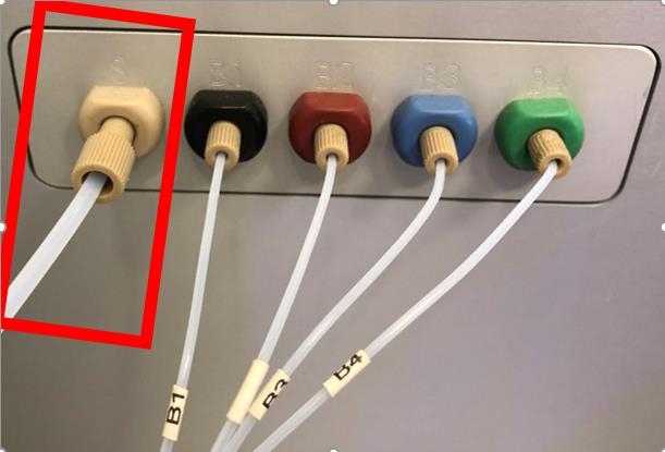
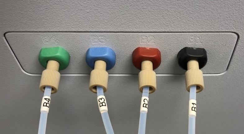
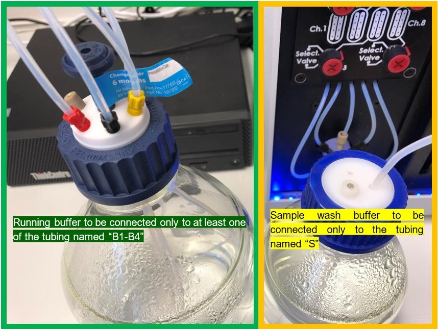
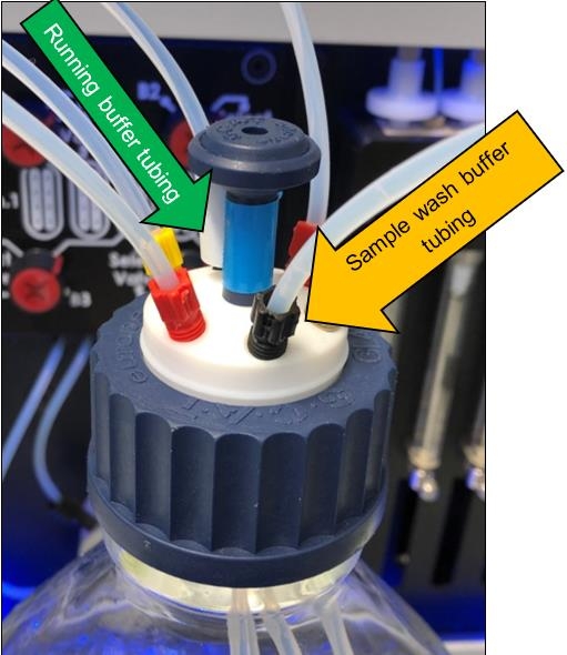
During an experiment it is recommended to connect the running buffer only to at least one of the tubing named B1B4 at the left system housing panel or the left housing panel of the buffer box.
Any standard buffer can be used, e.g. PBS (137 mM NaCl, 10 mM Phosphate, 2.7 mM KCl, and a pH of 7.4) or Hepes-Buffer with or without additives like cofactors or DMSO, Tween20, etc.

2.1.1.2 Sample Wash buffer

In addition it is also recommended to connect the sample wash buffer only to the tubing named S at the left system housing panel. Always use just ddH2O or ddH2O + Tween20 (0.005 – 0.05%).

Figure 2-3: Recommended usage during an experiment. Tubings coming from connections with letters B1 - B4 should be inserted into the running buffer bottle. Tubings coming from the connection with the letter S should be inserted in a separate bottle containing ddH2O (0-0.05% Teen20)

Notes:

  1. Always use ddH2O with or without tween (0.005 – 0.05%) as sample wash buffer.
  2. Never insert the running buffer tubing and sample wash buffer tubing into the same bottle, when running an experiment.
  3. Please replace the sample wash buffer bottle frequently. And do not refill it, when it is getting empty.
  4. Rule of thumb: Make fresh buffers (running buffer and wash buffer) every day.

2.1.2 Usage during Cleaning, e.g. Sanitize and Desorb

While performing the system cleaning it is recommended to insert the running buffer tubing and sample wash buffer tubing into the same bottle containing the cleaning solution.

2.1.2.1 Cleaning solutions for Sanitize and Desorb

Table 2-1: Details on composition of cleaning solution and their storage

Solution Composition Storage
Desorb 1 0.5% (w/v) sodium dodecyl sulphate (SDS) Room temperature
Desorb 2 50 mM glycine, pH 9.5 4-8 °C
Sanitize 0.5% (v/v) sodium hypochlorite Room temperature
ddH2O ddH2O Room temperature
2.1.2.2 Cleaning commands

The Desorb- as well as the Sanitize Routine can be found in the R3 Control software under the “Maintenance-Section”. Each cleaning command consists of three individual cleaning steps, requiring three individual cleaning solutions.

Figure 2-4: Screenshot from the R3 Control Software. Desorb and Sanitize tile
2.1.2.2.1 Desorb

The Desorb routine washes the system with Desorb 1, Desorb 2 and ddH2O. Each solution will be used for ~41 min. for an internal cleaning of the microfluidics. In total the routine takes ~2h.

2.1.2.2.2 Sanitize

The Sanitize routine washes the system with Sanitize, ddH2O and running buffer or ddH2O. Each solution will be used for ~41 min. for an internal cleaning of the microfluidics. In total the routine takes ~2h.

For both cleaning routines it is recommended to insert all active tubing (running buffer tubing and sample wash buffer tubing) into the same bottle for each individual cleaning solution

Figure 2-5: Recommended usage during cleaning. All tubing should be inserted into the same bottle.

2.1.3 Usage during long-term Standby and Shutdown

When putting the instrument into long-term Standby or Shutdown the following procedure is recommended.

2.1.3.1 Long-term Standby
  1. Initially a system cleaning (Desorb + Sanitize) is recommended as described in section 3.
  2. Prime the instrument 5x with ddH2O.
  3. Turn system into Standby-Mode (Maintenance Section within R3 Control Software).
  4. Keep both tubing (running buffer tubing and sample wash buffer tubing) in the bottle containing ddH2O.
Figure 2-6: Screenshot from R3 Control Software showing the Standby Mode tile as well as the hints on the liquid consumption during Standby
2.1.3.2 Shutdown
  1. Initially a system cleaning (Desorb + Sanitize) is recommended as described in section 3.
  2. Prime the instrument 5x with ddH2O.
  3. Close software.
  4. Turn off the instrument, power switch is located at the back panel of the instrument.
  5. Turn off the PC.
Figure 2-7: Illustration of the power switch, located at the back panel of the instrument
2.1.3.3 Awake from Shutdown
  1. Connect a bottle with freshly prepared ddH2O to the system and insert all tubing into the
    bottle.
  2. Turn on the PC, wait until operations system has fully initialized.
  3. Turn on the instrument, power switch is located at the back panel of the instrument.
  4. Start the Control Software.
  5. Prime the instrument 5x with ddH2O.
  6. Perform system cleaning (Desorb + Sanitize) is recommended as described in section 3.

For long-term Standby as well as Shutdown it is recommended to insert all active tubing (running buffer tubing and sample wash buffer tubing) into the same bottle for each individual cleaning solution but also while system is in long-term Standby or in Shutdown.

2.2 Tips on sample preparation

2.2.1 Buffer (Hints from SensorCon-2)

  • Adjust pH properly
  • Degas: Prevents air spikes within your experiment
  • Filter (0.2 µm): Prevents clogging of microfluidics
  • Use at room temperature: Buffer will “outgas” inside the system, if stored and used at lower temperatures (e.g.: 4°C)

Rule of thumb: Make fresh buffer every day!

2.2.2 Decrease non-specific binding (Hints from SensorCon-2)

  • Use detergent
    • Prevents non-specific binding from proteins to each other
    • Add detergent after degassing running buffer (pour gently)
    • e.g.: 0.05% P20
  • Use BSA
    • Prevents non-specific binding to tubing, microfluidics
    • e.g.: 0.1 mg/mL

2.2.3 Increase compound solubility (small molecule assays)

  • Use DMSO (dimethyl sulfoxide)
    • Add after degassing running buffer (pour gently)
    • Match sample and running buffer concentration
    • e.g.: 1-5% DMSO

2.2.4 Prevent evaporation

  • Use plate sealers and caps

2.2.5 Proper concentration range

  • Start with low concentrations, increase step-wise
  • E.g.: 0.1-10 × KD, having 6-8 dilutions
  • Kinetic runs: e.g. 3-fold dilution
  • Equilibrium runs / Steady State Analysis: e.g. 2-fold dilution

2.2.6 Proper repetition

  • Fewer single concentrations, but more repeats

2.3 Tips on experimental setup

2.3.1 Include reference surfaces

  • Needed for single subtraction of data
  • Subtraction of non-target interaction events (e.g. non-specific binding on sensor surface)

Options for reference surface:

  • Activated/blocked surface (minimum)
  • Similar non-specific protein (good)
  • Non-specific or modified version of surface sample (best)
Figure 2-8: Schematic illustration of an example surface setup. Next to the target (Spot D), there are three different reference surfaces used: A mutant (Spot C), a similar non-specific reference protein (Spot B) and the activated/ blocked sensor surface (Spot A).

2.3.2 Include Zero injections

  • Needed for double subtraction of data
  • Subtraction of solution sample events (e.g.: bulk shifts, baseline drift)
  • Minimize bulk shifts (Dissolve solution sample in assay buffer (same environment for association and dissociation)

Options for zero injections:

  • Direct Kinetic (Zero injections every 2-4 concentrations)
  • Capture Kinetic
    • Separate zero cycle (recommended)
    • Embedded zero (exceptionally)
Figure 2-9: Example for a capture kinetic with separate zero cycle. Within the first capture cycle a dedicated zero injection is performed, followed by a cycle including the same surface samples with an injection of solution sample.

2.3.3 Include Start-Up Cycles (Hints from SensorCon-2

  • Increases surface equilibration
  • Improves data-quality

Options for Start-Up Cycles:

  • If no regeneration is needed: 5-15 buffer injects prior the experiment
  • If regeneration is needed: 3-5 regeneration / buffer inject cycles prior the experiment
Figure 2-10: Raw data from buffer injection over a surface (from SensorCon-2). While increasing the number of injects, the artefacts per injection decrease.

2.3.4 Proper Flowrate

  • Capture, e.g. surface sample
    • Low flowrate to save sample, e.g. 10 µL/min
  • Solution Sample Inject
    • High flowrate to prevent mass transport limitation
    • e.g 25-50 µL/min
  • Regeneration
    • mostly the contact time is crucial
    • e.g 25-50 µL/min

2.3.5 Proper Injection time (Hints from SensorCon-2)

  • Association: Inject long enough to see curvature in the top 2 concentrations (e.g. 10 – 600 seconds).
  • Dissociation: Observe the dissociation long enough to see at least 5% dissociation ( e.g. 10 seconds – 12 hours).

Table 2-2: Recommended association and dissociation times

Type of solution sample Association Time Dissociation Time
Solution sample, activation, immobilization 180-600s 0s
Surface sample, capture, immobilization 180-600s 0s
Solution sample, blocking, immobilization 180-600s 0s
Solution sample, capture 10-240s 0-60s
Solution sample, analyte 10-600s 10-3600s
Solution sample, regeneration 10-180s 0-60s
Solution sample, common 10-60s 0-60s
Solution sample, solv. corr. 10-60s 0-30s

2.3.6 Proper regeneration conditions (Hints from SensorCon-2)

  • Start with gentle conditions and enhance slowly
  • Short contact time (contact time 5-15 s)
  • Retest binding

2.3.7 Proper regeneration conditions

  • Proteins / Antibodies: acid; 5-150 mM
  • Peptides / nucleic acids: SDS; 0.01-0.5%
  • Nucleic acids: 10 mM NaOH
  • Lipids: isoPrOH:HCl 1:1
  • See in Table 2-3 for possible regeneration solitions
Table 2-3: Possible regeneration solutions [source: https://www.sprpages.nl/kinetics/regeneration#].
(Click on the table to switch it's size.)
Strength Type of bond
Acidic Basic Hydrophobic Ionic
Weak ph > 2.5 ph < 9 ph < 9
10mM glycine/HCl 10mM HEPES/NaOH 25–50% ethylene glycol 0.5–1 M NaCl
1–10 mM HCl 0.02% SDS
0.5M formic acid
Intermediate ph 2 – 2.5 ph 9 – 10 ph 9 – 10
0.5M formic acid 10–100mM NaOH 50% ethylene glycol 1–2M MgCl2
10mM Glycine/HCl 10mM Glycine/NaOH 0.5–0.5% SDS 1–2M NaCl
10mM Glycine/HCl
0.85% H3PO4
Strong ph < 2 ph > 10 ph > 10
1M formic acid 50–100mM NaOH 25–50% ethylene glycol 2–4M MgCl2
10–100mM HCl 6M guanidinechloride 0.5% SDS
10–50mM Glycine/HCl 1M ethanolamine
0.85% H3PO4
0.1% trifluoracetic acid